


TEC-8A-24V-PID-HC Temperature Controller
The TEC-8A-24V-PID-HC Temperature Controller is designed for precise temperature control within the -70 to 70 degrees Celsius range. With stabilization accuracy of up to +/-0.05 degrees Celsius, it ensures exceptional temperature stability and reliability.
- Read reviews (1)
Downloads
Volume discounts
| Quantity | Price | Discount | You Save |
|---|---|---|---|
| 2 | $70.20 | $7.80 | Up to $15.60 |
| 5 | $66.30 | $11.70 | Up to $58.50 |
| 25 | $62.40 | $15.60 | Up to $390.00 |
| 50 | $46.80 | $31.20 | Up to $1,560.00 |
| 100 | $42.90 | $35.10 | Up to $3,510.00 |
Product description
About the TEC-8A-24V-PID-HC Programmable Temperature Controller
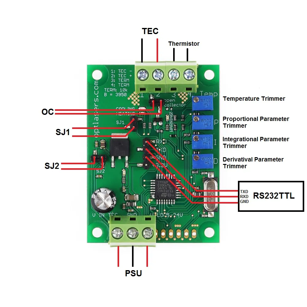
The TEC-8A-24V-PID-HC controller makes it possible to control temperature in the range of -70 to 70 degrees Celsius. The UART interface enables reading temperature setpoint, actual temperature, and PID parameter values. The driver includes a thermistor with a BETA value of 3950 for accurate temperature measurement.
With its versatile functionality, this controller offers both heating and cooling capabilities without the need for jumper configuration. Additionally, it includes an open collector output, allowing it to serve as a signal for other devices. Clear LED indicators provide visual feedback on the heating or cooling activity.
Designed with compact dimensions, user-friendly regulation, and versatility, this controller finds widespread application across various industries. It is specifically designed to work with 12 V Peltier modules, but is compatible with modules operating within the 5 to 24 V supply voltage range.
Operating in PWM mode (Pulse Width Modulation), the controller is capable of handling currents up to 8 A. It utilizes the 10k NTC B3950 temperature sensor, and the default temperature setpoint is configured at 20 degrees Celsius.
Thanks to the adjustable PID controller parameters, this driver can be adapted to suit nearly any system. Depending on the system's inertia, a properly calibrated driver ensures precise temperature maintenance with an exceptional accuracy of up to ±0.05 degrees Celsius.
Recommendations and requirements
- We recommend the use of power cables with a minimum cross-section of 0.5 mm2
- The Peltier module's current depends on the supply voltage used. Common modules typically operate at 12-15 V, with the maximum current specified by the module symbol. For example, "12708" indicates a voltage range of 0-12 V and a maximum current of 8 A.
Protection
This temperature controller has no reverse polarity protection. Reverse polarity at the power supply will permanently damage the temperature controller.
If the temperature is higher than 70 degrees Celsius or lower than -70 degrees Celsius, the driver will not power the Peltier module. Additionally, the open collector output is grounded.
Reviews
Okay
It's impressive how this dedicated controller maximizes the performance of my Peltier modules. It's a perfect match.