Driver for Laser Diodes - Infrared
Product Description of the HPLDD 60A Driver for Laser Diodes
This is a professional driver designed for high power infrared laser diodes. It can work with 20, 40, and 60 W CS-mount 808 nm, 940 nm, and 980 nm laser diodes as also with other similar diodes.
With this driver for laser diodes, you can power one diode or several diodes in series as also one diode stack which requires higher working voltages. In the recommendation section, there is a formula for maximum input voltage. Separate laser diode supply voltage input and logic input voltage allow minimizing the switch-on resistance of a power MOSFET. The inner layer of the heatsink is made of copper and helps in fast heat transmission. The outer body of a heatsink, made of aluminum, is isolated from all signals on the driver, including a GND signal. It allows mounting the driver directly to the metal components in case of additional cooling needed. Analog input allows for the modulation of the current flowing through the diode up to 5/20 kHz (depending on the version). Two potentiometers are used to set the values of maximum diode current and offset current. Attached to the driver is connector and pins which are used to power and control the unit as also the M5 stainless steel screws.
The capacitor bank is available as an additional part of the driver. It is needed when weaker PSU is used.
Technical Data
| Parameter | 5 kHz | 20 kHz |
|---|---|---|
| Modulation frequency (kHz) | 5 | 20 |
| Modulation voltage range (V) | 0–5 V | |
| Maximum diode current (A) | 60 A | |
| Current set by default (A) | 10 A | |
| Soft-start (ms) | 2000 ms | |
| Laser diode supply voltage (V) | 3–24 V | |
| Transistor type | High power N-MOSFET | |
| Maximum offset current (A) | 20 A | |
| Logic supply voltage (V) | 12–15 V | |
| Connector material | Cooper | |
| Power connectors screws | Stainless steel M5 | |
| Inner heatsink material | Cooper plate | |
| Outer heatsink material | Aluminum | |
| Isolated from all signals heatsink | Yes | |
| Mounting holes raster (mm) | 85 × 50 mm | |
| Mounting holes diameter (mm) | 5.5 mm | |
| Maximum power dissipation (W) | 200 W | |
| Current monitor | 10 mV / 1 A | |
| Current set by default (A) | 10 A | |
| Dimensions (mm) | 50 × 95 × 35* | |
* 39 mm dimension is different from a capacitor bank. For more information please check the mechanical data section.
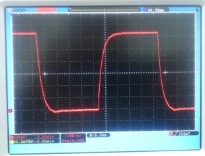
Current flowing through high power silicon diode. 62 A, 20 kHz signal. Measured on sense resistor using current monitor output.
How to Connect the HPLDD 60A Laser Driver
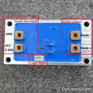
Pinout of the driver
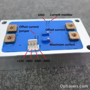
Pinout of the driver
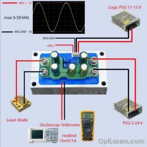
Schematic connections
How to Switch On the Driver
- Connect the logic plug, diode power line, and laser diode, don’t turn on the PSU yet.
- Be sure that modulation input is switched off.
- Switch on 12 V logic input.
- Switch on diode mainline.
- Start modulation on (ANG 0–5 V).
How to Switch Off the Driver
- Switch off modulation input.
- Switch off the diode power line.
- Switch off 12 V input.
How to Calculate the Power Dissipation
Although the maximum power dissipation of this driver for laser diodes is 240 W at 25 °C, it is recommended to calculate power dissipation and consider applying additional heatsink.
The power dissipated in the driver can be calculated from the formula:
Power dissipation = (Uin − n × Ud) × I
Where:
Uin — Total diode line input voltage
n — Number of diodes
Ud — Diode working voltage
I — the used current
For example: Using 5 V PSU and single 980 nm diode (1.9 V working voltage) with 50 A current:
Power dissipation = (5 V − 1 × 1.9 V) × 50 A = 3.1 V × 50 A = 155 W
Recommendations and Requirements
The supply voltage range depends on the number of laser diodes used in series. For one laser diode in which operating voltage is around 2 V, the maximum diode input voltage should not exceed 5 V. For two diodes which operating voltage is around 4 V, maximum diode input is 8 V and so on. Therefore the maximum input voltage is given by the formula:
VCC DIODE MAX = (Number of diodes in series) × (Each diode operating voltage) + 4 V.
Always power the logic with 12 V before powering up the diode line. Because GND of the diode line and GND of the logic input are connected in the driver, always remember to connect GND of the diode line directly to the GND of a PSU with thick wires.
Always use a high-quality power supply unit with low ripple voltage. Adding a large capacitor at the driver input is strongly recommended, but it depends on PSU, wires cross-section and their length. The capacitor used during the tests was 1000 uF 25 V.
You should be very careful not to cause a short circuit between the + (VCC) of the power nor + (LD) supply and − (GND) of the logic input or current monitor input, as a thin GND logic paths can be irreparably damaged.
Modulation input can be used as TTL input with its logic levels of 0 V and 5 V or as an analog input. Analog modulation means that by using 2.5 V on ANG input you get 50% output power, analogically by using 4 V you get 80% output power, etc.
We recommend the use of power cables with a cross-section of at least 4 mm2.
Protection
Due to high current flowing through the paths we minimized the voltage drop on the driver and there is no reverse polarity protection. We recommend using the LASORB protection device mounted close to the diode or at least a high power silicon diode connected backward.
The driver's body is isolated from all signals of the driver and can be mounted directly to the metal heatsinks or other metal parts.
The analog input is protected by a 5V1 Zener diode on occasion there appears the voltage higher than 5 V. Despite everything, this input should not be used with higher voltages.
Dos and Don'ts
- Pay attention to proper cooling.
- Do not touch the unit during operation.
- Do not exceed specified parameters.
Mechanical Details of the Heatsink
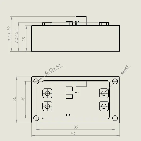
Dimensions of the Heatsink
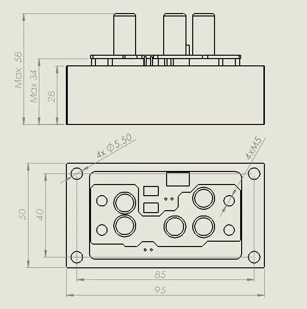
Dimensions of the Heatsink with 25 V Capacitor Bank
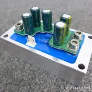
HPLDD 60A
Driver with 25 V Capacitor Bank
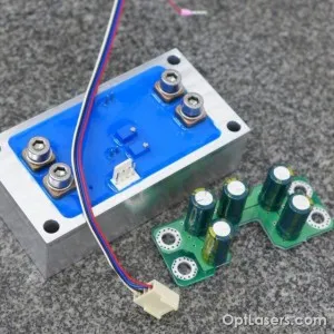
Driver with 25 V Capacitor Bank
Related Laser Drivers on Our Online Store
Also, check the category Laser Diode Drivers.