Opt Lasers Product Manuals

X-Carve Laser Upgrade - Wiring Setup
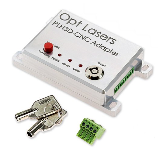
- Unpack the Opt Lasers PLH3D-CNC Adapter. Cut the zip ties.
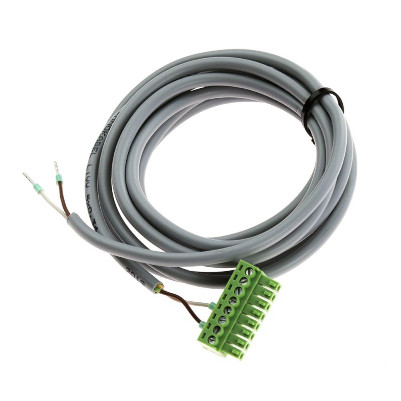
- Connect the 2 core wire Adapter inputs to the spindle outputs on your X-Controller.
- Connect the Brown wire to "Spindle (PWM)".
- Connect the White wire to "GND".


- Connect the the other end of the 2 core wire Adapter to the PLH3D engraving and cutting laser inputs.
- Connect the Brown wire to pin 2 "PWM/TTL Input".
- Connect the White wire to pin 4 "GROUND".

- Open the cable drag chain on the X-Carve.
- Use a small flat head screwdriver to open the drag chain.

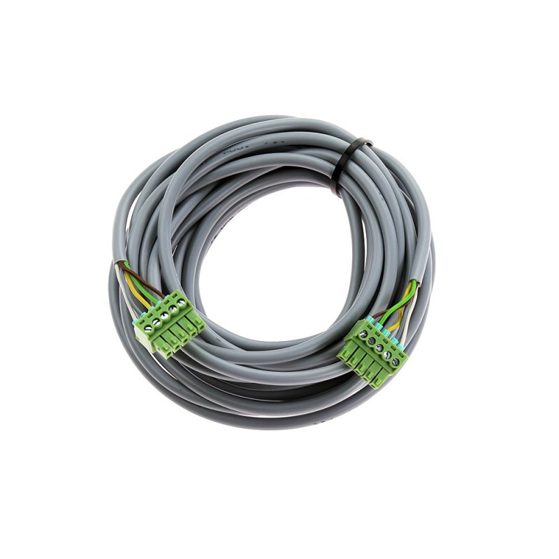
- Feed the 5-core wire from the Adapter through the entire length of the drag chain. Let it come out near the Mounting Plate on the spindle holder.
- Make sure that there is enough wire when the Z-Axis is lowered all the way.
- Close the cable drag chain on the X-Carve.
- Ensure that you plug the terminal blocks in the correct way into:
- the female part of the LaserDock

- the Adapter Output
NOTE: The pinout for the Adapter Output or LaserDock should mirror the Laser Modules pinout.


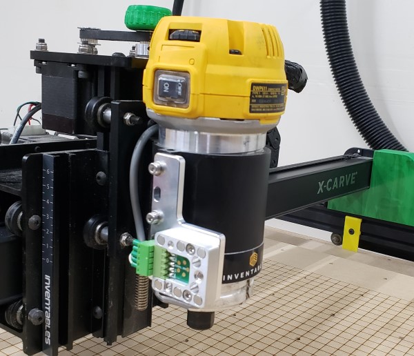
- Attach the laser module to the spindle mount.

- Put on your safety glasses and ensure nothing unintended is in the path of your laser.
- Ensure that the Adapter is Off. Connect Power Supply to the Adapter.
