


LPLDD-5A-24V-TP Laser Diode Driver
Single channel 5 A 3.3-24 V laser diode driver with thermal protection. Based on many inquiries from customers, this version of the LPLDD-5A-24V driver is equipped with thermal protection which switches off the laser diode circuit if the temperature exceeds 45 degrees of Celsius. The thermal sensor is included. Additional LEDs signalize the current status of the laser controller.
Technical Data
Product Description
About the LPLDD-5A-24V-TP Laser Diode Driver
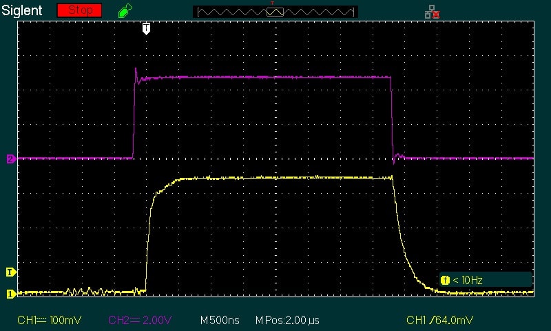
The LPLDD-5A-24V-TP Laser Diode Driver is a professional laser diode driver featuring thermal protection to ensure optimal performance of laser diodes and prevent overheating. This versatile driver allows for adjustable output current ranging from 0 to 5 A and enables diode current modulation at frequencies up to 100 kHz. An example test with the 100 kHz square-wave input signal modulation is shown below.
The driver incorporates a robust thermal protection system to safeguard the laser diode from overheating. Under normal operating conditions, the green LED remains illuminated as long as the thermistor measures a temperature below 40 degrees Celsius. If the temperature exceeds 40 degrees Celsius, the red LED starts blinking. When the temperature reaches 45 degrees Celsius, the red LED stays on, and the laser diode driver automatically switches off until the temperature drops below 40 degrees Celsius. If the connection between the driver and thermistor is lost or interrupted, both LEDs will blink, requiring a reset of the driver by disconnecting and reconnecting the power supply.
With broad compatibility, the LPLDD-5A-24V-TP can power a wide range of laser diodes available on the market, including those with wavelengths of 405 nm, 445 nm, 520 nm, 638 nm, 650 nm, 808 nm, and 980 nm, with optical powers up to 5 W.
Example Test
- 6 W NUBM44 laser diode (at 3.3 A )
- 15 cm long 0.35 mm2 wires
- 12 V input voltage (@ 10% duty cycle)
- 80 x 80 x 20 heat sink on power MOSFET
Recommendations and requirements
- To power the laser diode driver using a single power supply in the range of 7.5-24 V DC, ensure the jumper is connected. However, if you are using a low voltage diode (e.g., 3 V), two power supplies are required, and the jumper should be disconnected. It is important to match the power supply voltage closely to the laser diode's requirements.
- For voltages lower than 3.3 V the input voltage is given by the formula:
Vin = 0,2* I + Vd - Vin - input voltage
- Vd - diode working voltage
- I - operating current
- Take great care to avoid short circuits between the + (VCC) of the power supply and -(GND) of the logic input or monitor input, as this can irreparably damage the thin logic GND paths.
- The modulation input can be utilized as a TTL input with logic levels of 0 V and 5 V, or as an analog input. Analog modulation allows adjusting output power by using specific voltage levels (e.g., 2.5 V for 50% output power, 4 V for 80% output power, etc.). This input can also be used as PWM input. The only requirement is that the base frequency of the PWM signal is in the range of 5-20 kHz.
- We recommend the use of power cables with a cross-section of 0.1*I mm2, where I is the operating current.
- Proper cooling of the power MOSFETs should be provided by screwing them to a metal heat sink. Without cooling, MOSFETs may be damaged and laser diodes may be burned.
Protection
The laser diode power circuit is safeguarded against reversed polarity using a high current Schottky diode with low forward voltage, protecting the laser diode from incorrect voltage connections while minimizing heat loss.
To safeguard the analog input, a 5V1 Zener diode is incorporated to handle voltages exceeding 5 V. However, it is essential to avoid using higher voltages with this input.