Professional Laser Driver Solutions
Laser Driver for Laser Diodes — Product Description
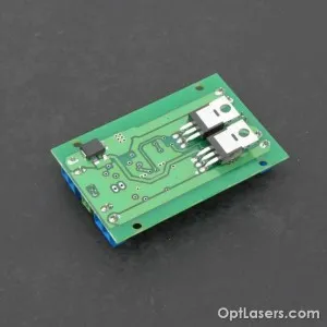
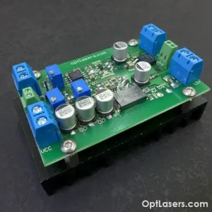
LPLDD 5A PID Laser Driver
This is the 3rd version of a professional driver for laser diodes with a built-in digital temperature controller using the PID algorithm. Its size allows for mounting it in small devices such as compact laser projectors. The driver is available in two versions. One includes a heatsink, the second one is without it and is dedicated to users who would like to use their own heatsink or optic plate. We intentionally resigned from a plug connector powering the circuit because experience shows that soldering the wire is the only sure way to avoid the problems associated with oxidation of contacts and arcing, particularly when a current of 15 A can flow through the wires.
Despite its small size, the driver is able to work with thermocouples (Peltier modules) such as 12706, 12708, 07113, and many others that draw up to 15 A of current. Despite the high current, thanks to using PWM the controller does not heat up. Used PID algorithm learns the behavior of the system, hence quicker reacts to changes in temperature and provides higher accuracy of stabilization. The driver easily handles all laser diodes of up to 5 W, and at the customer's request, it is possible to customize the driver up to 10 A version. Separate laser diode supply voltage input and TEC input enable the selection of any components the driver can work with. Analog input allows for the modulation of the current flowing through the diode up to 100 kHz. Two potentiometers are used to set the values of maximum diode current and bias current. The third potentiometer is responsible for setting the setpoint temperature in the range of 0 to 40 degrees Celsius. The possibility to power laser diodes of any wavelength and control the Peltier modules with a rated voltage from 3.3 to 16 V and current up to 15 A make this driver truly unique and extremely versatile.
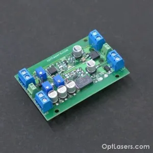
New features
- Added screw connectors (ARK) — smaller size, easy to connect the wires
- Added test jumper — the possibility of switching on the driver without external analog signal
- Added current monitor output — the possibility of measuring the current while the device is working
- Added signal diodes: diode, TEC, warning
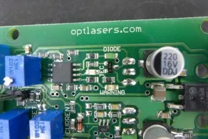
Added labels on the board — more intuitive and easier to set
Technical Data
| Parameter | Value |
|---|---|
| TEC maximum current | 15 A |
| TEC supply voltage | 3.3–16 V |
| Maximum diode current | 5 A |
| Current set by default | ~2000 mA |
| Laser diode supply voltage | 7–16 V |
| Modulation voltage (analog) | 0–5 V |
| Maximum modulation frequency | 100 kHz |
| Current monitor | 100 mV / 1 A |
| Soft-start | Yes — 2000 ms |
| Temperature sensor | 10 k NTC thermistor |
| Temperature stabilization accuracy | ±0.1 °C |
| TEC indicator | Yes — blue LED diode |
| Laser diode indicator | Yes — red LED diode |
| Over-temperature protection | Yes >50 °C |
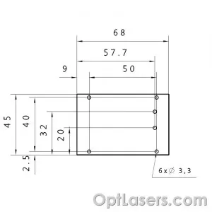
| Board dimensions | 68 mm × 45 mm |
| Mounting holes distance | 40 mm × 50 mm |
| Transistor type | N-MOSFET |
| Maximum heat dissipated | 40 W |
How to Connect the LPLDD 5A PID Laser Driver
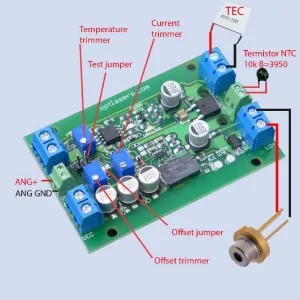
Connecting “Test jumper” allows to switch on the driver without external analog signal.
While Offset jumper is not connected the Offset trimmer is not working.
The temperature trimmer allows setting the working point of TEC in the range of 0–40 degrees Celcius.
How to Power Supply the LPLDD 5A PID Driver
Thanks to the dual power line of the driver it is possible to the power supply the driver in various ways. In order to power, the logic part of a driver diode line must be always connected to proper voltage 7–16 V. TEC part cannot work alone.
- Laser diode driver with the single PSU
If the driver is used without TEC, a single power supply 7–16 V can be used. Analog modulation should be 0–5 V.
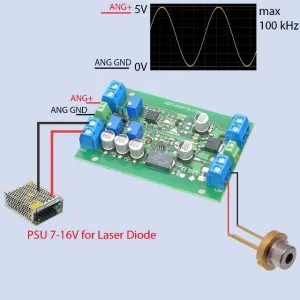
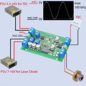
- Laser diode driver with the TEC and two PSUs.
If the driver is working with TEC, the double power supply can be used. The one for laser diode should be 7–16 V, meanwhile the second for TEC should be 3.3–16 V. Analog modulation should be 0–5 V.
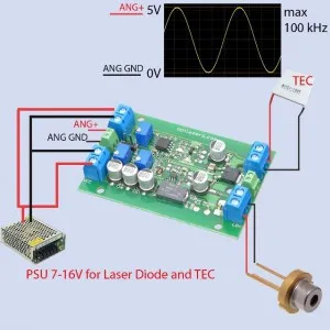
- Laser diode driver with the TEC and the single PSU.
If 7–16 V PSU is used, it can power supply both, laser diode as well as TEC. Analog modulation should be 0–5 V.
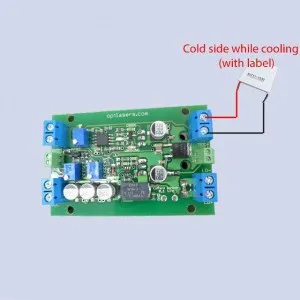
Connecting the TEC to the Driver
If one connects the TEC accordingly to the picture below, the side with the label will be cold during the driver’s work. If one connects the cables in the reverse order, the side without a label will be cold.
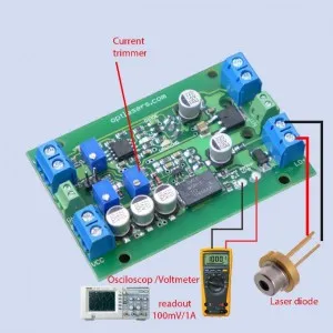
Checking the Current Set on the Driver
The driver is fitted with a current monitor. A safe test of the current can be made without using a laser diode. Instead of using the laser diode, use a test load resistor (0.5–1 Ω 5 W) with a silicon diode then check/set the current using the current monitor. Regulate the current with “Current trimmer”. Each 100 mV measured by a voltmeter/oscilloscope means 1 A will be flowing through the laser diode.
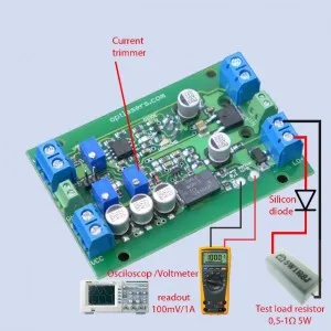
It is also possible to check/set the current with the use of a laser diode. In such a situation, the measurement is the same as before.
We recommend to check/set the current using a test load resistor because it is much safer and will harm the laser diode.
Recommendations and Requirements
The minimum diode input voltage should be higher or equal to 7 V, in other situations it is given by the formula:
Vin = 0.4 × I + Vd + 0.6 V
- Vin — input voltage
- Vd — diode working voltage
- I — desired maximum current
While using with high power infrared diodes bigger heatsink should be used. Be aware that using a 2 V diode with 5 A current together with 12 V PSU is producing a lot of heat (5 A × (12 V − 2 V)) = 50 W of heat. This is why for this kind of operation 7.5 V supply should be used.
Modulation input can be used as TTL input with its logic levels of 0 V and 5 V or as an analog input. Analog modulation means that by using 2.5 V on ANG input you get 50% output power, analogically by using 4 V you get 80% output power, etc.
You should be very careful not to cause a short circuit between the + (VCC) of the power supply and − (GND) of the analog input, as a thin GND analog path can be irreparably damaged.
The MOSFET/MOSFETS must be isolated from the heatsink/plate with a silicon pad as well as the plastic sleeve. A short circuit between MOSFET and heatsink/plate can damage the driver and can be dangerous for the Laser Diode.
We recommend the use of power cables with a cross-section of at least 0.5 mm2.
Protection
The circuit responsible for powering a laser diode is protected against reversed polarity. High current Schottky diode of an extremely low forward voltage secures the laser diode against connecting reversed voltage with the aim of protecting frequently the most expensive part of the entire device — a laser diode. In turn, the low forward voltage does not cause excessive heat loss during normal operation.
The analog input is protected by a 5V1 Zener diode on occasion there appears the voltage higher than 5 V. Despite everything, this input should not be used with higher voltages.
A microcontroller ensures the proper operation of the entire system.
At the start, the microcontroller is checking the connection with a thermistor. If there is no thermistor used the WARNING LED is blinking but the driver is still working. If the connection with the thermistor is lost during normal work, the microcontroller turns off the laser diode supply circuit and does not allow for its further load. It also switches off the DIODE LED and switches on the WARNING LED. The TEC line is also switched off. The same situation happens when the thermistor reaches a temperature above 50 degrees Celsius.
The driver is fitted with a two-second soft-start designed to protect the laser diode against switch-on effects.