Please click here for the newest version with documentation.
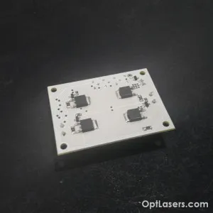
Product Description:
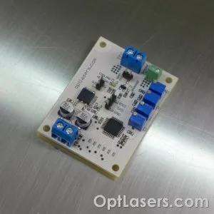
This is an improved digital temperature controller. The new version is able to heat and cool without changing any jumpers. The controller is available in two versions of the program: Basic and Advanced. Beyond the basic functionality, advanced version offers the possibility to set various parameters of the controller using UART.
It has also open collector output which allows to use it as a signal for other devices. Additional LED diodes show heating or cooling activity. Also, the dimensions of the PCB are smaller and mounting holes have been added.
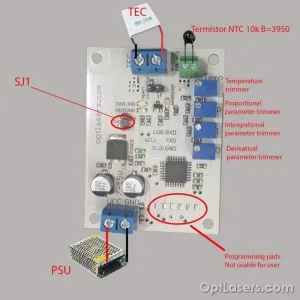
You can use UART to read the temperature setpoint, actual temperature and PID parameters values. To this end, just use the GND, TXD and RXD outputs. To read the proper value of the temperature you have to use a thermistor with BETA value of 3950 which is also included with the driver.
Its small size, simplicity of regulation and versatility make it widely used in many areas. It is dedicated to work with 12 V thermocouples (Peltier modules) yet it does well with all modules whose supply voltage falls in the range of 7,5 to 15 V.
With the use of four trimmers, the temperature setpoint as well as values of the PID controller parameters can be set. The controller operates in PWM mode (Pulse Width Modulation) and can control currents of up to 8 A. For the temperature sensor, it uses a standard 10k NTC thermistor. By default the temperature setpoint is set to 20 degrees Celsius.
Due to the possibility to set the parameters of a PID controller, the driver can be adapted to almost any system. Depending on the inertia of the system, properly adjusted driver is able to maintain the desired temperature with an accuracy of up to +- 0.05*C.
The current flowing through the Peltier cell depends on the supply voltage used. Most of the common modules should be supplied with the voltage of 7,5 to 15V, and the maximum current that flows through them is defined by a cell symbol. For example, the 12708 symbol means that the cell should be supplied with the voltage of 0 to 12V, and a maximum current which can be used amounts to 8A.
The driver is working in TTL 5V standard and will not work correctly in TTL 3,3V standard.
Technical Data:
| TEC maximum continuous current (A) | 8 |
| Input Voltage (V) | 7,5 - 15 |
| Temperature stabilization accuracy | ±0,1°C |
| Cooling or heating work | Yes |
| Temperature sensor | 10k NTC B=3950 |
| Temperature range to set with trimmer | 0 - 50°C |
| Heating indicator | Yellow LED diode |
| Cooling indicator | Blue LED diode |
| Power supply indicator | Green LED diode |
| Lack of thermistor connection indicator | Red LED diode |
| Power supply indicator | Yes - LED diode |
| Over 55 degrees Celsius indicator* | Yes - Warning LED diode |
| Radiator required | No |
| Heat sink required | No |
| Dimensions (LxW mm) | 45 x 60 |
| Mounting holes (LxW mm) | 37 x 52 |
| Mounting holes diameter (mm) | 3,2 |
*Set by default. Can be changed in advanced version of the program.
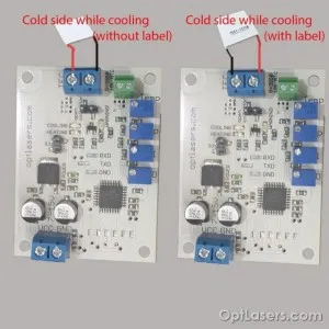
How to connect the TEC controller
It is possible to connect TEC in two ways. Depending on the chosen connection, different side of the TEC can be cold while cooling:
Advanced program
Opened/Not connected SJ1 jumper mode
-Adjustment with the use of four trimmers. Trimmers allow to set PID parameters, as well as to set the temperature working point;
- Work in the temperature setpoint range of 0 to 50 degrees Celsius;
- Warning diode blinking in the range of 45 to 70 degrees Celsius;
- Grounded open collector (OC), warning diode ON and Peltier current OFF, over 70 degrees Celsius;
- When temperature drops from 70 degrees the driver goes back to normal work.
Closed/Connected SJ1 jumper mode
- Adjustment with use of UART port
Using PC and USB->RS232 TTL it is possible to send and read parameters to/from the regulator. While using this mode, trimmers are not working, but user gets full control of any of the parameters. Additionally it is possible to set lower/upper threshold which is checked by the driver (OC).
Connection:
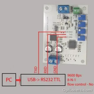
TXD should be connected to RXD
RXD should be connected to TXD
GND should be connected to GND
Connection parameters:
- 9600 bits / second
- 8 data bit
- even parity: no
- stop bits: 1
- flow control: no
Parameters:
Tsetpoint - temperature set by the user
P - proportional parameter 0.0 - 20.0
I - intergrational parameter 0.0 - 20.0
D - derivatival parameter 0.0 - 20.0
Tmin - lower threshold which is checking by the driver (OC)
Tmax - upper threshold which is checked by the driver (OC)
Tmeasured - currently measured temperature
Cooling - 0 or 1 showing the status of the controller
Heating - 0 or 1 showing the status of the controller
OC - 0 or 1 status of the open collector
PWM% - 0 to 100, duty cycle in %
Readout is given as:
Tsetpoint PID Tmin Tmax Tmeasured Cooling Heating OC PWM%
Example:
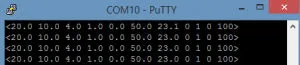
Configuration format: < Tsetpoint PID Tmin Tmax >
Example: <10 4.5 1 30.6 0 60.7>
<> are needed to make a correct command
Additional commands:
o - take single readout
R - automatic readout ON
r - automatic readout OFF
a - switch OFF TEC supply
A - switch ON TEC supply
- normal work when the measured temperature is in the range of Tmin and Tmax, when out of range the OC is grounded and warning led is ON, Peltier module is working normally (cooling or heating);
- when the measured temperature goes back to Tmin,Tmax range, OC become disconnected and warning diode is OFF.
Basic program
- Adjustment with the use of four trimmers. Trimmers allow to set PID parameters, as well as to set the temperature working point;
- Work in the temperature setpoint range of 0 to 50 degrees Celsius;
- Warning diode blinking in the range of 45 to 70 degrees Celsius;
- While using Basic program SJ1 is not working;
- Grounded open collector (OC), warning diode ON and Peltier current OFF, over 70 degrees Celsius;
- When temperature drops from 70 degrees, the driver goes back to normal work;
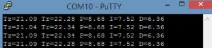
- The parameters set with UART
Tz - Temperature setpoint
Tr - Temperature measured
P - proportional parameter 0.0 - 20.0
I - intergrational parameter 0.0 - 20.0
D - derivatival parameter 0.0 - 20.0
Example:
Recommendations and requirements
We recommend the use of power cables with a minimum cross-section of 0.5mm2.
Protection
The system detects a lack of connection with the thermistor and then switches WARNING LED on. As long as the connection is lost, the driver will not take any action and the open collector output is grounded.
If the temperature is higher than 45 degrees Celsius, WARNING LED starts to blink but the driver is working normally.
If the temperature is higher than 70 degrees Celsius, WARNING LED is ON and the driver will not power the Peltier module. Also the open collector output is grounded.
Store - product page
- TEC controller 7-15V 0-8A Warming/Cooling