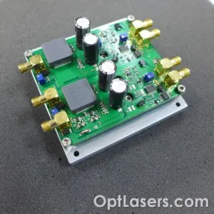
Product Description:
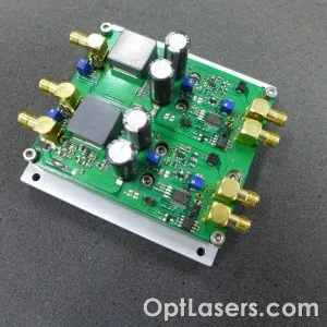
PLDD 10 A is a professional pulse driver designed for powering a laser diode. You can adjust parameters such as pulse width, diode current, and compliance voltage. The driver can also work in CW mode and deliver 10 A constant current to a laser diode.
The driver can work with laser diodes which operating voltage is below 9 V. The supply voltage of a driver is 12 V to 32 V. Maximum pulse current is 10 A. The driver is protected against too long impulses - on request we can modify the software or make a project of a similar driver.
Features:
- laser diode current monitoring output
- overcurrent protection
- automatic thermal shutdown
- low noise
- transient suppression
- closed loop analog PID controlled
- output shorting switch using P-mosfet to protect a laser diode
- Pulsed mode or CW with analog modulation mode
- coaxial connectors
Technical Data:
| Supply Voltage (V) | 11-36 |
| Max Output Current (A) | 10 |
| Output Current Range (A) | 1-10 |
| Outputs Compliance Voltage (V) | 1.5 – 9 |
| Outputs Pulse Width (msec) | 0.1 – 50 |
| Rise Time / Fall Time (µsec) | ≤ 10 |
| Repetition Rate | Single shot |
| Current Drop (%) | ≤ 1 |
| Modulation Input voltage range (V) | 0 - 5 |
| Supply Voltage (V) | 11 - 36 |
| LED indicators | Power ON, Output ON |
| Controls | - Trigger ON/OFF switch
- Input ON/OFF switch |
| Connectors type | SMA |
| Dimensions (LxW mm) | 86 x 73 (only PCB) 97 x 89 (PCB with connectors and heatsink) |
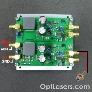
How to connect the PLDD 10A
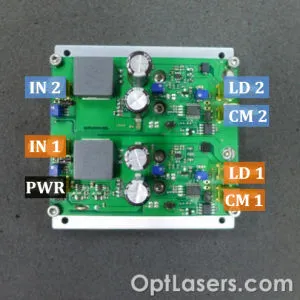
(Orange - channel 1, Blue - channel 2)
Connectors:
PWR – Main power supply (11-36 V)
IN 1, IN 2 – Input signal (0 - 5 V)
LD 1, LD 2 – Laser diode output
CM 1, CM 2 – Current monitor output (50 mV/1 A)
Note! The configuration of potentiometers and jumpers are very important. Please check their configuration before connecting power. The driver has two independent channels and is powered from a single power connector. Each channel can be set to different compliance voltage and has an independent current monitor output.
Before connecting the laser diode, make sure the driver is properly configured. Best suggested way is to prepare measurements using a test load.
To perform the test, connect the semiconductor diode in series with a resistor (0,5R 5W) and check the waveform on the oscilloscope – monitor output. The voltage of 50 mV is equal to 1 A current. The monitor output is as polarized as the power connector, the input of the oscilloscope should be set in a high impedance state (10 X probe).
The analog input must be in the range of 0 to 5 V, while the input supply voltage in the range of 12 V to 32 V.
How to configure PLDD 10A
Potentiometers:
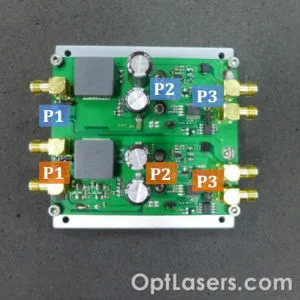
(Orange - channel 1, Blue - channel 2)
P1 – DC-DC converter compliance voltage (clockwise rising voltage), in the range of 1.5 V-5 V or 1.5 V-10 V, set by SW1 jumper
P2 – Output current (counterclockwise rising current) 1 A – 10 A
P3 – Output signal length (clockwise rising length), in the range of 100 µs-50 ms or 100 µs-2 ms, set by SW3 jumper
Jumpers:
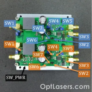
(Orange - channel 1, Blue - channel 2)
SW_PWR – Main power jumper (left = ON; right = OFF) (use it only when the device is disconnected from a power source)
SW1 – DC-DC converter compliance voltage (open = 1.4V-5.4 V; closed = 1.4 V-10.5 V)
SW2 – Trigger slope (open = rising Edge; close = falling Edge)
SW3 – Output signal length adjustment range (open = 100 us-50 ms; close = 100 us-2 ms)
SW4, SW5, SW7 = analog/digital mode (digital = SW4 close, SW5 open, SW6 open; analog SW4 open, SW5 close, SW7 close)
SW6 – Disable 10% PWM limit (open = 10% limit is on; close = limit is off)
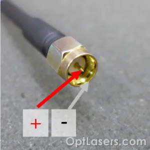
How to connect laser diode
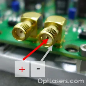
While connecting the laser driver please be sure that you do not change polarization. The wrongly connected driver can be irreparably damaged.
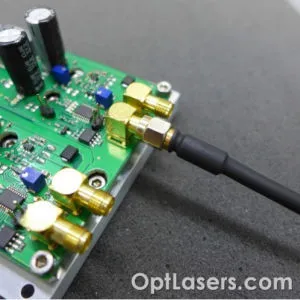
An example connection of a cable with SMA connector. SMA connectors are attached to the driver for user convenience.
LED status indicators of PLDD 10A
LED 1 shows analog/TTL input status. When LED is ON it means that the driver input is in triggering the signal, LED 2 shows when the laser is ready for work - duty of the input signal is correct.
Max duty of the input signal is 10%. On request, we can change this value. You can also switch off a duty signal guard and start using the driver in CW or analog modulated mode.
LED 3 indicates if the input duty cycle does not exceed 10%. L4 LED indicates whether the driver is powered correctly.
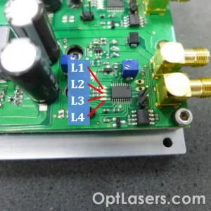
L1 – Input pulse readout
L2 – Ready to trigger
L3 – Blinking = Exceeded 10% pulse width; LED is ON = driver overheat (>70*C)
L4 – Power
Checking the current set on the driver
Safe test of the current can be made without using a laser diode. Instead of a laser diode, use a test load resistor (for example 0,5R 5W) in series and check the waveform on the oscilloscope – monitor output. The voltage of 50 mV is equal to 1 A current. By potentiometer, the current should be adjusted to the desired value. The monitor output is as polarized as the power connector, the input of the oscilloscope should be set in a high impedance state (10 X probe).
We recommend to check/set the current using a test load resistor because it is much safer and will limit the possibilities of mistake and burning the laser diode.
Recommendations and requirements
The supply voltage must be within the range of 12 V to 32 V.
The heat sink is isolated from the MOSFETs and the driver so it can be directly mounted on another metal surface.
If the driver is warming up too much, we recommend installing the heatsink which will dissipate the heat.
We recommend the use of power cables with a cross-section of at least 1 mm2.
The driver should not be used in dusty places in order to provide better heat dissipation.
The driver should be operated in temperatures up to 40 degrees C.
Protection
The output of the laser diode is properly secured. Transil diode protects against reverse voltage and short current peaks. Resistor connected parallel to the laser diode protects against condensing the charge. The built-in P MOSFET shorts the output going to laser diode when the driver supply voltage is disconnected.
The driver has a built-in thermistor which protects it against overheating.
If the driver heats up too much, you can use an additional fan for cooling.
Please note: as a manufacturer, we can make a customized version of a driver. If you have any questions, please contact us at [email protected]